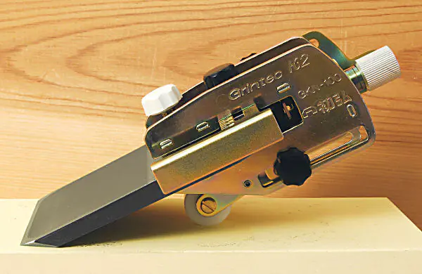
Special grinding aid Grintec K2 for Japanese plane blades
The grinding aid Grintec K2 is designed with the characteristics of Japanese plane blades in mind. Japanese plane blades are much shorter and thicker compared to Western plane blades. The thickness tapers from the back end to the bevel. The sides are also not always parallel. The name "Grintec" is a composite of the English words "grind" and "technology".
For example, the illustrated blade from Tsunesaburo is 67.6 mm wide at the back and only 65.2 mm at the beginning of the bevel. The thickness is 9 mm at the back and 6 mm at the beginning of the bevel. The length is 102 mm - measured without the bevel. The bevel has an angle of 28°. Due to the lateral chamfer at the bevel, the cutting edge has a width of 59 mm. These characteristics present a particular challenge for the design of a sharpening guide.
Max. blade thickness 10.5 mm
Min. blade width 40 mm
Max. blade width with stop 83 mm
Max. blade width with stop removed: theoretically unlimited, practically probably around 150 mm
Max. blade length 120 mm
Min. blade length 60 mm
Labels on the plane iron
Warnings
- When clamping and unclamping the cutting tool, adjusting, sharpening, and testing the edge, there is a risk that the tool may fall and cause injuries, such as to the feet. Therefore, always work at a workbench and ensure a stable stance. Wear work trousers and safety shoes.
- Avoid contact with the edge when using the sharpening aid.
- Ensure adequate lighting. Work in an area that is not accessible to children.
- Store the sharpening aid and cutting tools in a place inaccessible to children during and after work.
Precautions
- When sharpening, the sharpening stone must be securely fixed to the workbench.
- Place the sharpening stone in front of you, hold the cutting tool and sharpening aid securely with both hands, and observe the process.
- Ensure that the roller of the sharpening aid does not slip off the stone.
- Do not alter the design of the Grintec K2. Do not use the sharpening aid for other tasks.
- Use the Grintec K2 as described in this user manual.

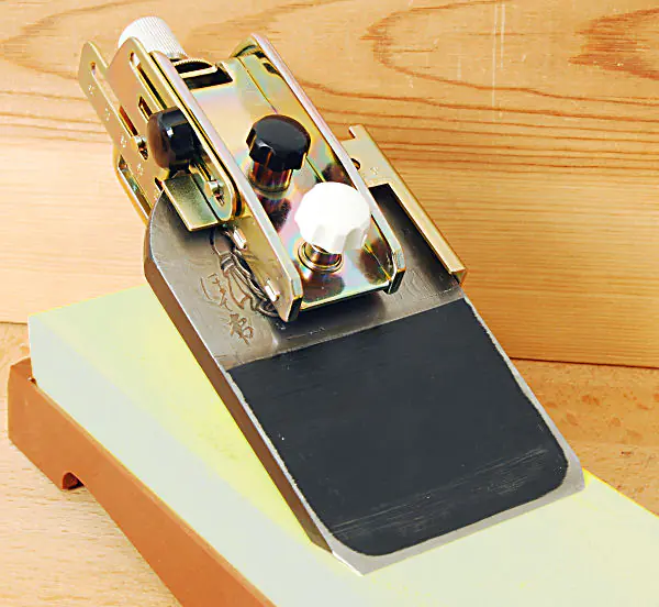
Functions of the Grintec K2
As shown in Fig. B 1a and B 1b, the two sides of the plane iron are called mirror side (hasaki-men) and back (hamoto-men). The angled surface at the edge is referred to as bevel (kenma-men, literally translated as "grinding surface"). The intersection of the back and the bevel is called bevel end (hamoto, literally "beginning/origin of the edge"). The sides of the plane iron are referred to as flanks here. The point where we strike to adjust the plane iron is called head. By striking with the adjustment hammer, the head of the plane iron deforms, referred to here as "deformed area".
The angle between the extension of the bevel and the back is called bevel angle, the distance between the two flanks of the iron is iron width, and the distance between head and bevel end is iron length.
- deformed area of the back
- back
- side/flank
- iron width
- deformed area
- head
- bevel angle
- iron length without bevel
- back
- bevel end
- bevel
- edge
- mirror side
About Sharpening Stones
- It is crucial that the bevel lies flat on the sharpening stone and that the angle between the sharpening stone and the chisel is maintained precisely. The sharpening aid Gintec K2 enables both a solid resting position and an accurately maintained sharpening angle. We refer to sharpening that adopts the existing bevel angle of a plane iron as junkaku kenma.
- It is important that the bevel angle matches the shape/geometry of the plane body exactly. However, the bevel angle can change significantly due to repeated sharpening, necessitating a correction. With the Grintec K2, you can sharpen the iron at a previously determined angle or correct an existing bevel angle. We refer to sharpening in this function as hakaku shitei kenma.
- During the final honing of the iron, the entire bevel can be worked/polished, but this is quite labor-intensive. With the Grintec K2, you can reduce the effort while achieving an extremely fine edge. We call this function choshiage kenma.
- By slightly lifting during honing, the edge becomes less sensitive and the service life is increased. We refer to applying a micro-bevel with the Grintec K2 as marume kenma, literally translated as "rounding sharpening".

Sharpening new plane blades
Depending on the condition of the plane iron, use a sharpening stone with coarse, medium, or fine grit. Ensure that the surface of the sharpening stone is completely flat. You cannot achieve good results with a surface that has become hollow due to wear. There are several methods for truing your sharpening stone. You can true it on a concrete slab with aggregate, rub two sharpening stones against each other, or use one of our truing blocks. By repeatedly turning the sharpening stone, you can avoid uneven wear.
Fig. B3a flat surface
Fig. B3b surface hollowed out by wear
Posture when Sharpening
The bevel angle depends on the design/geometry of the plane. We recommend measuring and noting the bevel angle before sharpening a new plane iron. This helps if the bevel angle needs to be corrected later.
It sometimes happens that the bevel on a new plane iron is not flat. In this case, during the first sharpening, not the entire bevel will contact the sharpening stone. First, use a stone with a coarse grit until the contact area extends over the entire bevel.
Finger position

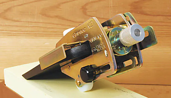
The parts of the sanding guide - top view
L 1: left middle finger
L 2: left index finger
L 3: left thumb
R 1: right middle finger
R 2: right index finger
R 3: right thumb

The parts of the sanding guide - view from the side
- Rotatable reference scale for adjustment range 0.0 to 0.5 mm
- Notch for accurately determining the adjustment read at (1)
- Fine adjustment screw for bevel angle
- Marking for standard setting (kijunsen = standard line)
- Locking screw for movable roller
- Adjustable side stop for setting the blade width
- Scale for reading the blade width
- Locking screw for side stop
- Screw for fixing the plane iron
- Housing
All screws are tightened clockwise to lock, turned counterclockwise to loosen.

The parts of the sanding guide - guide for angle adjustment
- Locking screw for setting the blade length
- Guide part of the stop located on the opposite side
- Attachment of the sharpening aid roller Sharpening aid roller
- Nut of the locking screw for movable roller Scale for setting the bevel angle Scale for setting the blade length Movable stop for setting the blade length

junkaku kenma - adoption of the existing bevel angle of a plane blade
- Gauge for determining the bevel angle
- Scale for determining the iron length and width

This method is applied when the existing angle of the plane iron is considered correct.
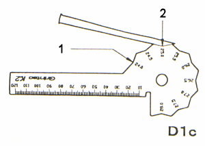
The included gauge is used to measure the plane iron. The iron length and width are determined as shown in Fig. D1a and D1b. The bevel angle is determined as in Fig. D1c by holding the bevel against the gauge and selecting the appropriate angle. In our example, the plane iron has a width of 75 mm, a length of 95 mm, and a bevel angle of 25 degrees. For a bevel angle outside the spectrum, please refer to H.
Fig. D1a:
1) Measured iron width
2) Scale
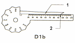
Measure the length of the blade (1) without its bevel using the included gauge. Example here: 95 mm.
1) Plane blade
2) Measured blade length without bevel
Setting of the side stop
Measure the bevel angle by finding the correct cutout (2). If no light gap is visible on either the bevel side or the underside of the iron, you have found the correct bevel angle. Example here: 25 mm. Japanese irons have a hollow on the mirror side (top side in the plane), referred to as "Ura." This does not play a role in this measurement. However, the backside (bottom side in the plane) of some Japanese plane irons is also concavely shaped. Do not measure the angle in the middle of the iron, but close to the side edge!
1) Cutouts for a total of 9 angles in 0.5 mm increments from 24 - 28°
2) Example result 25°

Setting of the depth stop and the roller
Loosen the locking screw (3) for the stop (1) and set the measured iron width on the scale (8) - in this example 75 mm. The scale is read directly on the side housing sheet (2). Then tighten the screw again. If the iron is wider at the back than at the front at the bevel, take this larger value.
- Adjustable side stop for setting the iron width
- Housing
- Locking screw for side stop
- Locking screw for setting the iron length/depth stop
- Standard line
- Screw for fine adjustment
- Locking screw for movable roller
- Scale for iron width
Turn the fine adjustment screw (6) until the front edge of the knurled screw is at the standard line (5).

Attachment of the planer blade
Loosen the locking screw of the depth stop (6) and the roller (4). Set the determined iron length without bevel of 95 mm and the determined bevel angle of 25 degrees using the scales, and then tighten both locking screws again. If the bevel angle exceeds 28 degrees or falls below 24 degrees, please proceed analogously to H. Then tighten both screws again.
- Scale for setting the iron length
- Adjustable stop for setting the iron length
- This is where the length value and angle value meet
- Nut of the locking screw for the adjustable roller. The angle scale is stamped on this.
- Scale for setting the bevel angle
- Locking screw for the depth stop

Fine adjustment of the sharpening angle
Insert the plane iron (3) so that it touches the side stop (1) and depth stop (4) and secure it by tightening the locking screw (2). The housing has some play for possible deformations at the head of the plane iron (see Fig. C1c) to avoid contact here. When adjusting the plane iron with a hammer, it can sometimes be significantly compressed at the head over the years, forming bulges. However, if the deformation is larger, the plane iron cannot be properly clamped in the sharpening aid. In this case, you should first eliminate the deformation at the head of the plane iron, e.g., with a file.
- Adjustable side stop
- Screw for securing the plane iron
- Plane iron
- Adjustable depth stop

Sharpening process
If you proceed as described, the sharpening angle should correspond quite closely to the bevel angle of the plane iron. For an even more precise adjustment, you should - as shown in Fig. D6 - place the sharpening aid with the clamped iron onto the gauge and check if the bevel (4) lies exactly on the gauge. If a gap appears at the edge, turn the fine adjustment screw (1) slightly clockwise. If there is a gap at the end of the bevel, turn it counterclockwise accordingly.
- Fine adjustment screw for bevel angle
- Roller
- Plane iron
- Bevel must lie flat
- Gauge

Repeated sharpening
Position the sharpening aid so that the roller (3) and bevel (2) are on the stone. Then move back and forth several times and check again. If the material removal at the edge is too strong, turn the fine adjustment screw slightly counterclockwise. If grinding occurs more at the end of the bevel, turn accordingly clockwise. Adjust the sharpening aid to ensure even sharpening. With this setting, continue sharpening until the entire bevel is ground to the edge. After that, continue sharpening on a fine honing stone. Finally, the plane iron is released again and, if necessary, the mirror side of the iron is honed.
- Grinding stone surface
- Bevel
- Roller
hakaku shitei kenma - Sharpening with a fixed bevel angle, i.e., correction of an existing bevel angle

Setting of the depth stop and the sliding shoe
In this method, the existing angle of a plane iron is not taken into account because it is worn down or the bevel angle is to be changed.
We explain the procedure using the example of a plane iron with a width of 75 mm and a length of 95 mm, which is to be ground with a bevel angle of 25 degrees.
Setting the side stop
Loosen the locking screw of the side stop (3), set the stop to 75 mm using the scale, and tighten the locking screw again.
- Adjustable side stop
- Housing
- Locking screw for side stop
- Locking screw for depth stop
- Standard line
- Adjustable depth stop
- Fine adjustment screw for bevel angle
- Locking screw for movable roller
- Scale for reading the iron width
Fine adjustment
Turn the fine adjustment screw (7) as shown in Fig. E1, so that the front edge of the knurled screw is aligned with the standard line (5).
Fixing the plane iron and sharpening
Loosen the locking screws for the depth stop and the sliding shoe that guides the roller. Set the scale of the depth stop to an iron length of 95 mm and the scale of the sliding shoe to a bevel angle of 25 degrees, then tighten the locking screws again (see Fig. E3). If the bevel angle exceeds 28 degrees or falls below 24 degrees, please refer to section H.
- Scale for setting the iron length (depth stop)
- Scale mark 95 mm and scale mark 25° must meet
- Angle scale of the sliding shoe
choshiage kenma - Honing or Sharpening

Pulling off
Before honing (also called "sharpening"), first bring the plane iron into a condition as described to the right of illustration D7 or E3.
Condition before honing (sharpening)
Rotate the reference scale so that the notch of the adjustment screw is at zero.
- Rotatable reference scale for adjustment range 0.0 to 0.5 mm
- Set the notch on the adjustment screw to 0
- Ribbed adjustment screw
Adjustment with the adjustment screw
Turn the adjustment screw clockwise until the notch is at 0.2. The reference scale indicates the change in the bevel angle. The bevel angle increases by 0.2 degrees when the adjustment screw is turned from 0 to 0.2 to the right.
4. Rotatable reference scale for adjustment range 0.0 to 0.5 mm
5. Ribbed adjustment screw
6. Setting the notch to a value of 0.2
Repeated stripping
Microbevel (literally: rounding sharpening) - increase edge durability
 - increase edge durability")
Bevel angle outside the scale range of this setting gauge
First, bring the iron into a condition as described next to the illustrations D7, E3, or F4.
Microbevel
Here, a different angle is used during the forward and backward movement. During the forward movement, as shown in Fig. G1, the sharpening aid is guided so that the roller touches the stone. When pulling back, it is lifted slightly, as in Fig. G2, so that the angle reaches about 45 degrees towards the end of the stone. Repeating this movement about 5-10 times will create a microbevel.
Notes on the Microbevel
- Use a fine sharpening stone
- If the angle is increased during the forward movement, the edge will be damaged.
- Do not perform the described movement more than ten times.

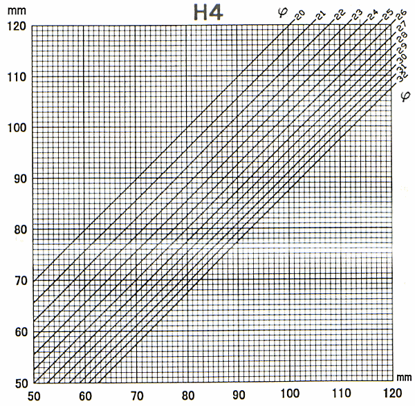
Use of the conversion graphic
With the Grintec gauge, bevel angles between 24 and 28 degrees can be measured. The scale for setting the bevel angle also indicates this range. If the bevel angle is outside this range, that is, above 28 or below 24 degrees, the angle can be determined as follows and the stops can be adjusted.
- Back of the plane iron
- Degree scale
- Bevel

Setting of the depth stop and the sliding shoe

As shown in Fig. H3, the bevel angle is set to 26 and the depth stop to 103.7, and fixed with the locking screws. With the conversion chart, the required value (for setting the depth stop) can be determined, while the bevel angle is set to 26 degrees.
| H: | Scale for setting the iron length |
| R: | Scale for setting the bevel angle |
| 26 x 103.7: | The markings 103.7 mm and 26° must be exactly opposite each other |
Care
Related products

Available, delivery time: 1-3 businessdays within Germany